0 CommentsLeave a comment
Day: December 25, 2009
sci if reality…..sirens and flying cars
s i r e n s a n d f l y i n g c a r s
By Henryk Szubinski
IMAGHES ARE ORDERED ACCORDING TO NUMBER SEQUENCE AND THEN DESCRIBED IN GREATER DETAIL AT THE BOTTOM OF THE PAGE:
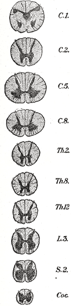
In Greek mythology, the Sirens (Greek singular: Σειρήν Seirēn; Greek plural: Σειρῆνες Seirēnes) were three dangerous bird-women, portrayed as seductresses, who lived on an island called Sirenum scopuli. In some later, rationalized traditions the literal geography of the “flowery” island of Anthemoessa, or Anthemusa,[1] is fixed: sometimes on Cape Pelorum and at others in the Sirenusian islands near Paestum or in Capreae.[2] All such locations were surrounded by cliffs and rocks. Sailors who sailed near were compelled by the Sirens’ enchanting music and voices to shipwreck on the rocky coast. When the Sirens were given a parentage they were considered the daughters of the river god Achelous, fathered upon Terpsichore, Melpomene, Sterope, or Chthon, the Earth, in Euripides‘ Helen 167, where Helen in her anguish calls upon “Winged maidens, daughters of the Earth”. Although they lured mariners, for the Greeks the sirens in their “meadow starred with flowers” were not sea deities
1

type flowers and also type deities from greece
2

3

car siren
but also a spinal eject path in the central nervous system
4
5

6

7
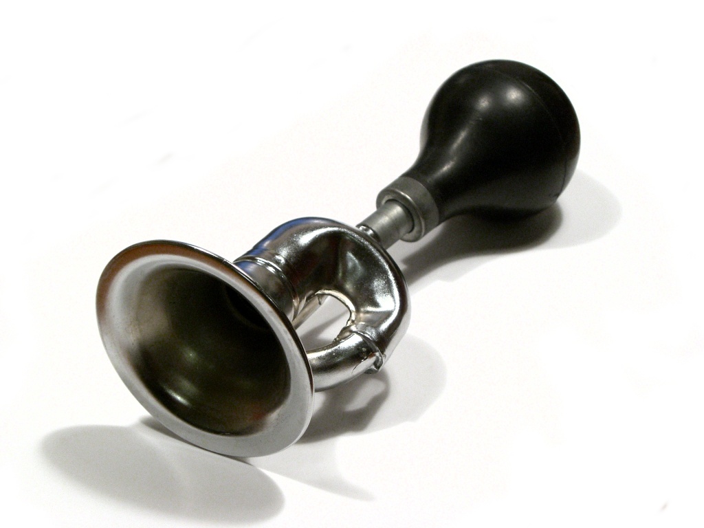
Automobile horns are usually electric klaxons, driven by a flat circular steel diaphragm that has an electromagnet acting upon it and is attached to a contactor that repeatedly interrupts the current to the electromagnet. This arrangement works like a buzzer or electric bell and is commonly known as “Sounding ones horn”. There is usually a screw to adjust the distance/tension of the electrical contacts for best operation. A spiral exponential horn shape (sometimes called the “snail”) is cast into the body of the horn to project the sound effectively. Sound levels are approximately 107-109 decibels, and current draw 5-6 amperes. Horns can be used singly, but are often arranged in pairs to produce a chord consisting of two notes, sounded together; although this only increases the sound output by 3 decibels, the use of two differing frequencies with their beat frequencies and missing fundamental is more perceptible than the use of two horns of identical frequency, particularly in an environment with a high ambient noise level. Typical frequencies of a pair of horns of this design are 500 and 405-420 Hz (approximately B4 and G#4).
1)
data here indicates that the process by which the occilative start of a left / right orientations = to a signal at each occilative new vector direction has some basic
2)
formats of recognition in the event should the sound wave of a horn and the vector alterance point be reposistioned in the calculational context of a string format.
3)
This data system where by the process in which the increased perimeters of such minimal string values as interactive with the driver is expandable to the level where
4)
the string = preconnective nose / tail of the vechciles quantal type interactions with it motion = 1 bit in disparsal of nose and tail = 1/2 q
5)
as such the problems of the data on a full stop is measurable by the porblematics of the vechicles vibrative stopp/ start mechanics whicle in motion:
6)
Data on the process by which the full zonal usage of the data on a audial signal being able to define the vector of motion as a interactive environment computer that can
7)
use the velocity as in the process of the absorbtions and emmissions at either tail or nose by a absorbancy valued waveform absorber and vector alterator to a new occilative response:
in the event where the generalisations of carbon molecules as a example of the energy or force potential inherent in the signal drive as having characteristics such as the motivation to alter gravity relations with a mass and its pulley system to the responsive primary waveform point as the parameter in which vector poosition is defined on the basis that the simltaneous vectorisations of a angle in turn is not implicative of a barrier or the stop motion of the implied levels of carbon usage =to the process by which the angle of alteration has similarities with a decreased heingt level on 4 points arranged in a rectangle.
The motion of the vechicle must then be controlled by a a.i unit that can define a car as a vtol but in much less constraints, much like a sci fi functional flying car.
sci fi reality…..the certainty responder
THE CERTAINTY RESPONDER
By Henryk Szubinski
freedoom of knowledge basis 5th law 5th frmework Chordis6
connect to evelopenet in primary fase or connect to non envelopment
is a question that regards a universal cobse format of 10 images in their background imagery as in 10 universes as in the following:

using a specially adapted type 1 keyboard to have 10 levels of communicative data inputs such as velocities points degrees vectors etc angles:as responsive to 1 cobe image pre line:
(APPENDED TO THE RIGHT)

cobe 1———————key board vector releif
cobe 2 ——————–key board vector indent
cobe 3——————–key board vector releif
cobe 4——————–key board vector indent
cobe 5——————–key board vector releif
cobe 6——————–key board vector indent
cobe 7——————–key board vector releif
cobe 8——————–key board vector indent
cobe 9——————–key board vector releif
cobe 10——————key board vector indent
this type of sequence defines the : USE THE RATIONAL APPROACH TO NON VIOLENTLY ACTIVE UNIVERSES:

A TYPE 1 IN SCREEN DECCEERATOR USED IN MOST UNIVRSAL VECHICULARITY
as the indications of at what angle to cyclate the interactions of the screen / monitor type localisations as decellerative effect = to the external decellerated perimeter connections by
r.p.m / points = deccellerative connect as squared value of point positions outside the spiral disk decellerator:
the basis of the usage of a point choice allocations in to a sequence of 10 points on each monitor as indicated and store= either indent or releif of the alternations of the sides of the monitor where a indent implies a indent on the opposite side of the creen monitor interface:
Light induced voltage alteration
From Wikipedia, the free encyclopedia
Light induced voltage alteration (LIVA) is a semiconductor analysis technique that uses a laser or infrared light source to induce voltage changes in a device while scanning the beam of light across its surface. The technique relies upon the generation of electron-hole pairs in the semiconductor material when exposed to photons.
[edit] Theory of operation
The device to be analyzed is biased using a constant current power supply. As the light source is scanned across the surface of the silicon, electron-hole pairs are generated. This causes subtle alterations of the operating characteristics of the device, which may result in slight changes to the power supply voltage. Any changes that are detected in the power supply voltage are noted and correlated with the position of the light source on the device. This allows the physical locations corresponding to power supply fluctuations to be mapped onto an image of the device. This provides the device analyst with specific locations at which the device may be examined for defects.[1]
the point to be made is to define the similar amounts of input of a point where the primary motivation = use the warp diagramm of the localised type inv tan spiral of the point distributions that are choosen in the 10 values:
By indicationg this type of localisations the chance that there might be a similar projective civilisation on the alternate side of the cobe imager point chices, is the same value by which =x
In the preceding description an important fact is ignored for the sake of simplicity: the dispersion of the energy. The reason that the energies of the states are broadened into a band is that the energy depends on the value of the wave vector, or k-vector, of the electron. The k-vector, in quantum mechanics, is the representation of the momentum of a particle.
The dispersion relationship determines the effective mass, m*, of electrons or holes in the semiconductor, according to the formula:
![m^{*} = \hbar^2 \cdot \left[ {{d^2 E(k)} \over {d k^2}} \right]^{-1}](https://i0.wp.com/upload.wikimedia.org/math/b/1/a/b1a58d209be0a622c0d09a2e24ce01fa.png)
The effective mass is important as it affects many of the electrical properties of the semiconductor, such as the electron or hole mobility, which in turn influences the diffusivity of the charge carriers and the electrical conductivity of the semiconductor
= to a input of suich points into specific parameters that the the similarity is defined on the secondary locative function; meaning that outside the inv tan spiral formats the distributions of choices as outside it =a chance by dividing the same input point designated specifics of a probability outside the ralm or zone of warp isolated friendly a.i responses.
the response from a delay in the alternate parameter outside the spiral but in the monitor zone
= 1/2 ( external chance 100 % )=the spiral certainty of a responder in that section.
